Table of Contents >> Show >> Hide
- What “Persistence of Vision” Really Means (and Why It Works)
- How a POV LED Globe Is Different from a Regular POV “Fan” Display
- Choose Your Build Style: Two Proven Architectures
- Bill of Materials: What You Actually Need (and Why)
- The Heart of the Illusion: Timing, “Ignition,” and Rotation Math
- Building the Rotor: Making Spin Your Friend (Not Your Enemy)
- Electronics Path A: Shift Registers Done Right
- Electronics Path B: APA102/DotStar for Full-Color POV
- Image Mapping: Turning a Flat Picture into a Spherical Illusion
- Troubleshooting: When Your Globe Looks Like a Haunted Jellyfish
- Smart Upgrades That Make Your Globe Feel “Next Level”
- FAQ
- Real-World Build Notes: The Experiences Makers Usually Have (Plus the Lessons They Earn)
- Conclusion
Ever wished you could hold the world in your hands… but, like, a glowing, floating, sci-fi version that makes your friends say “HOW is that even real?”
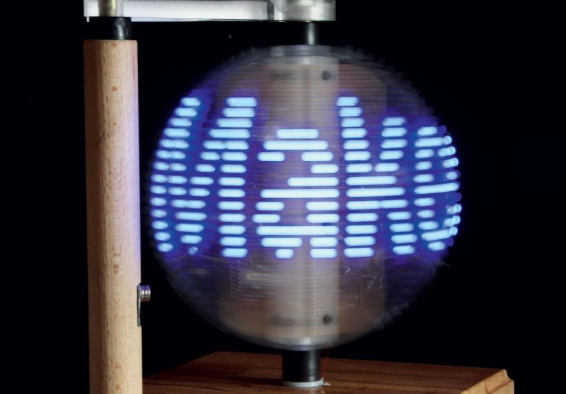
That’s the magic of a persistence-of-vision (POV) LED globe: a fast-spinning arc of LEDs that tricks your eyes into seeing a full spherical imagemaps, skulls, logos, animationshovering in thin air.
This guide breaks down how POV globes work, what the major design options are, and how to build one with fewer headaches and more “wow.”
We’ll lean on classic Make:-style mechanics (shift registers + a Hall sensor “ignition pulse”) while also showing modern upgrades like fast addressable LEDs
and microcontrollers that don’t panic when you ask them to do math at high speed.
Safety note: This is a spinning, wired, soldered project. Use eye protection, keep hair/sleeves away from rotating parts, and get adult supervision for drilling, cutting, or heating plastics.
What “Persistence of Vision” Really Means (and Why It Works)
Your visual system doesn’t update like a perfect digital camera. Instead, it blends rapid changes over short time windows.
In simple terms: if light flashes quickly enough, your brain merges the flashes into a steady image.
Vision researchers describe this as a flicker-fusion effectwhen a flickering stimulus becomes indistinguishable from continuous light at higher frequencies.
A POV display exploits that blending. You show a thin slice of an image at just the right position during rotation, then the next slice, then the next.
Your eyes “stitch” those slices together into a complete picturelike a flipbook made of photons.
The trick isn’t only speed; it’s timing. If your LED column is even a few milliseconds early or late, the image smears, wobbles, or looks like it was printed on a trampoline.
A good POV globe is basically a synchronization project disguised as a party trick.
How a POV LED Globe Is Different from a Regular POV “Fan” Display
Many POV projects start as a 2D “propeller” or “fan” display: a straight line of LEDs spins around a center point and draws a flat disc of pixels.
A POV globe adds a twist: instead of a straight line, you use a curved LED arc (a ring segment).
When that arc rotates around an axislike a planet spinningyou can create the illusion of a spherical surface.
In Make:’s classic approach, the globe is built from four major systems:
(1) the spinning LED rotor, (2) control electronics that drive dozens of LEDs using shift registers,
(3) a rotation reference sensor (commonly a Hall effect sensor + magnet) to “zero” each revolution,
and (4) software that converts an image into timed LED patterns that match the rotor’s speed and position.
Choose Your Build Style: Two Proven Architectures
Option A: Discrete LEDs + 74HC595 Shift Registers (Classic Make:-style)
This is the “old-school reliable” route: you place individual 5mm LEDs along a curved strip and drive them through 74HC595 shift registers.
The microcontroller sends LED states as serial data, then latches them so multiple outputs update together.
You get crisp on/off “pixels,” simple wiring patterns, and predictable timing.
- Pros: Very fast updates via hardware SPI, cheap parts, easy to understand at the signal level.
- Cons: More soldering, more physical assembly, single-color (unless you build RGB LED arrays and drivers).
Option B: Fast Addressable LEDs (DotStar / APA102) + Modern Microcontroller
Want full color, simpler LED wiring, and easier graphics? Use a strip or ring of DotStar/APA102 LEDs.
Unlike WS2812/NeoPixel-style LEDs (which are often too slow for high-quality POV), APA102-class LEDs use a clocked data protocol (SPI-like),
which generally supports higher refresh rates and smoother POV images.
- Pros: Full color, simpler LED chain wiring, easier bitmap/image workflows.
- Cons: Higher current draw, stricter power/noise requirements, some strips struggle at very high SPI clock rates on long runs.
If your goal is a “Make: magazine homage” with a clean engineering vibe, Option A is satisfying.
If your goal is a “tiny hologram Earth that can also become a dancing taco,” Option B will make you happier.
Bill of Materials: What You Actually Need (and Why)
Exact parts vary by design, but most POV globes share the same shopping cart categories.
Here’s a practical, buildable list with the purpose of each component:
Mechanical + Motion
- Rotor ring/arc: Polycarbonate (tough) or aluminum (stiff). Avoid brittle plastics that can crack under centrifugal load.
- Motor: A DC motor with enough RPM for smooth image “frames.” Many builders target 1000+ RPM territory depending on resolution.
- Shaft + coupling: A rigid shaft plus a flexible coupling helps reduce wobble from imperfect alignment.
- Bearings/support: A stable axle and bearings reduce vibration and make timing more consistent.
- Base/stand: Weight matters. A heavy base is like emotional support for spinning things.
Electronics (Classic Shift-Register Build)
- Microcontroller: Arduino Nano-class boards are commonly used for compactness.
- 74HC595 shift registers: One chip per 8 LEDs, chained to scale outputs.
- Current-limiting resistors: One per LED, sized for your LED type and supply voltage.
- Hall effect sensor + magnet: A “home position” trigger once per revolution for rock-solid timing.
- Capacitor (bulk): Helps smooth supply dips caused by rotation contacts or load changes.
Electronics (Addressable LED Build)
- APA102/DotStar LEDs: Fast, clocked addressable LEDs that behave well in POV applications.
- Microcontroller with strong SPI: RP2040, ESP32, Teensy-class boards, etc.
- Power delivery: A stable 5V supply sized for peak LED current, plus decoupling near the LEDs.
- Optional slip ring: If electronics are on the rotor, a slip ring can deliver power while spinning.
The Heart of the Illusion: Timing, “Ignition,” and Rotation Math
Here’s the core idea: your globe is a loop that repeats every rotation.
At a known angle, you start outputting the first column (or “meridian slice”) of your image, then the next, and so on,
so by the time the rotor completes a full turn, you’ve drawn the entire image once.
Step 1: Establish a Reliable “Zero” Point
A Hall effect sensor mounted on the rotor and a fixed magnet on the base is the classic solution.
Each time the sensor passes the magnet, you get a clean pulse that says: “New revolution starts NOW.”
This pulse can trigger an interrupt so your timing doesn’t drift while your code is busy doing other things.
Step 2: Decide Your Resolution
A globe image is typically described as:
vertical resolution = number of LEDs on the arc (how many “latitudes” you can show),
and horizontal resolution = how many timed slices per rotation (how many “longitudes” you draw).
Example: 40 LEDs on the arc × 150 slices per rotation = 6000 pixels per full globe frame.
That’s enough for recognizable shapes, text, and simple logosespecially if you choose bold graphics.
Step 3: Match Output Speed to Rotation Speed
If you spin at 20 revolutions per second (that’s 1200 RPM), and you want 150 slices per rotation,
you must output 20 × 150 = 3000 slices per second.
That means each slice budget is about 0.333 milliseconds.
This is why fast output methods matter. Hardware SPI can push bits quickly to shift registers or to APA102 LEDs.
Slower “bit-banged” methods often cause visible jitter or smeared images when speeds rise.
Building the Rotor: Making Spin Your Friend (Not Your Enemy)
The rotor is where mechanical reality tries to ruin your optical illusion. Your mission is to build something that spins smoothly, safely,
and consistentlybecause image stability depends on consistent speed and minimal wobble.
Material choice: Tough beats pretty
Polycarbonate is popular because it’s resilient and less likely to crack under stress. Aluminum works too, but shaping it cleanly can be harder.
Whichever you choose, make sure the arc is consistent, the LED spacing is uniform, and the mounting is rigid.
Balance isn’t optional
A slightly unbalanced rotor at high RPM becomes a portable vibration machine.
Builders often add small adjustable weights (screws/nuts) to tune balance.
If your stand walks across the table, that’s not “feature creep”that’s “stop immediately.”
Vibration control tips
- Use a flexible shaft coupling to reduce alignment stress between motor and rotor.
- Keep wires tidy and symmetricalrandom wire blobs can act like tiny unplanned counterweights.
- Add rubber feet or damping pads to the base to reduce resonance.
Electronics Path A: Shift Registers Done Right
The 74HC595 is an “8-bit serial-in, parallel-out” device: you clock in eight bits, then latch them to appear on eight output pins.
Chain five of them and you have 40 controllable outputs.
Why SPI is your best friend
SPI is built for fast, synchronous data transfer. Instead of toggling pins slowly in software,
you let the hardware handle the clocking. This keeps timing crisp and reduces jitter.
Current and brightness considerations
When you drive many LEDs, power and current limits show up fast.
Use correct resistors, avoid overloading chip outputs, and consider transistor driver arrays if you want ultra-bright LEDs.
A POV globe loves brightnessbut it also loves not burning out mid-demo.
Wiring sanity checklist
- Use a consistent ground scheme (common ground across controller, registers, LEDs).
- Keep data lines short and neat, especially on the spinning assembly.
- Add bulk capacitance near the load to buffer dips, especially if power transfer is imperfect.
Electronics Path B: APA102/DotStar for Full-Color POV
For full-color globes, APA102/DotStar LEDs are a common choice because they use separate data and clock lines,
enabling faster updates than single-wire addressable LEDs in many POV scenarios.
Many makers report that WS2812-style LEDs can look “ugly” or jittery at the refresh rates POV demands, while APA102 performs better.
But don’t crank the SPI clock to the moon
Faster isn’t always better. Some APA102 strips can become unreliable at very high clock speeds,
especially with long LED chains or imperfect signal integrity.
Practical builds often run stable at moderate SPI clocks and focus on clean wiring and good power delivery.
A modern workflow: bitmaps in, light sculpture out
Many newer POV builds convert a bitmap image into per-angle LED color data.
For example, a motorized POV display can read a bitmap file and “paint” it in the air by updating LEDs as the rotor turns.
This approach makes it easy to swap images without rewriting a ton of codeyour globe becomes a tiny stage for whatever pixel art you feed it.
Image Mapping: Turning a Flat Picture into a Spherical Illusion
A globe graphic is essentially a texture wrapped around a sphere. Your POV globe approximates that by rendering slices in time.
There are two common approaches:
-
Direct slice mapping: Treat your image as a rectangular map (width = slices per rotation, height = LEDs),
and output one vertical column per slice. -
Globe-aware mapping: Apply a projection (like equirectangular map logic) so continents don’t look stretched near the poles.
This produces a more “globe-like” Earth, especially at lower resolutions.
For early prototypes, direct slice mapping is plenty. Use bold, high-contrast shapes: thick text, simplified continents, chunky icons.
Tiny details will blur because your “screen” is literally moving through air while your eyes are trying to negotiate a peace treaty with physics.
Troubleshooting: When Your Globe Looks Like a Haunted Jellyfish
Problem: Image is stretched or squished
Your slice timing doesn’t match your actual rotation speed. Either measure RPM more accurately (using the Hall pulse interval)
or adjust the per-slice delay so the image width matches one full revolution.
Problem: Image “drifts” around the globe
Your “zero” reference is unstable. Improve magnet/sensor alignment, debounce the signal, and use an interrupt-based approach so the pulse is never missed.
Problem: Random flickers or missing pixels
Check power integrity and wiring strain on the rotor. Spinning assemblies can cause intermittent connections.
Add bulk capacitance near the LEDs and ensure ground connections are solid.
Problem: Vibration makes everything worse
Balance the rotor. Reduce wobble. Tighten what should be tight, loosen what should float, and don’t be afraid to rebuild the mount.
A stable image is usually a stable mechanical system firstand a clever codebase second.
Smart Upgrades That Make Your Globe Feel “Next Level”
- Wi-Fi control: Load images or messages from a phone (ESP32 builds do this well).
- SD card media: Store multiple animations and rotate them on a schedule.
- Closed-loop speed control: Measure RPM from the Hall pulse and adjust motor PWM automatically for steady speed.
- Slip ring cleanup: If you use a slip ring, add filtering and strain relief so spinning doesn’t become “random disconnect roulette.”
- Better mapping: Use projection-aware rendering so your Earth looks like Earth, not a slightly anxious egg.
FAQ
How fast does it need to spin?
Fast enough that slices blend into a stable image, and fast enough that your chosen resolution can be output within a single rotation.
Many builds land in the 1000+ RPM neighborhood, but the “right” speed depends on your LED count, slice count, brightness, and output method.
Do I really need a Hall effect sensor?
If you want a stable image that doesn’t drift, yes. You need a repeatable “start line” for each revolution.
A Hall sensor + magnet is a common, robust solution.
Can I use NeoPixels (WS2812) anyway?
You can, but POV projects often demand refresh behavior that isn’t NeoPixel’s favorite hobby.
If you want cleaner results, clocked LEDs like APA102/DotStar are widely preferred for POV-style displays.
Real-World Build Notes: The Experiences Makers Usually Have (Plus the Lessons They Earn)
The first time you power a POV globe, you’ll probably have a brief moment of pure confidencefollowed by the rotor wobbling like it’s trying to escape your desk.
That’s normal. A POV globe build tends to teach the same three lessons, no matter how experienced you are: balance matters, timing matters,
and your wiring will be personally offended by centrifugal force.
Makers often start by obsessing over the code, because code feels controllable. But the funniest (and most humbling) part of POV globes is how often the “bug”
is a mechanical issue wearing a trench coat. A slightly off-center coupling can make your image look like it’s slowly melting. A wire that tugs once per revolution
can create a repeating glitch that looks like a haunted longitude line. Even the base can matterif the whole stand vibrates, your Hall sensor alignment changes
and your “perfect interrupt timing” gets dragged into the chaos.
Another common experience: the brightness surprise. You think you’ll need every LED at maximum intensitythen you turn it on and realize your globe is bright enough
to signal aircraft. After the initial “wow,” builders usually dial brightness down to reduce power stress, heat, and flicker artifacts. It’s also common to discover that
bold graphics beat detailed graphics. The designs that look best are often the simplest: thick text, high-contrast icons, chunky continents, and big shapes that your eyes
can stitch together without doing overtime.
If you go the shift-register route, you’ll likely have at least one “why is nothing lighting up?” moment. Spoiler: it’s usually a polarity issue on one LED chain,
a missed ground connection, or a latch/clock line that’s one pin over. The good news is that systematic testing pays off fast: builders often test a single 74HC595 + 8 LEDs first,
then scale up. That gradual approach feels slow until you compare it with the alternative: wiring everything at once, then trying to debug a rotating bundle of mystery.
If you go full-color with APA102/DotStar, the emotional arc is different. You’ll get pretty visuals sooner, but you may discover new “fun” like signal integrity,
power injection, and the fact that long LED chains can be picky at very high clock speeds. The practical maker move is usually to choose stability over bragging rights:
run a solid SPI speed, keep wiring clean, and let the globe look great instead of “almost great but occasionally cursed.”
The best experience, though, is the moment it finally locks in: the Hall pulse hits, the slices align, the wobble settles, and suddenly there’s a floating image in mid-air.
People who’ve never seen POV in person will lean in and squint, because their brain is convinced you’re cheating. And in a way, you areyou’re cheating perception,
using timing and motion to paint pictures on nothing at all. It’s physics, it’s art, and it’s one of the most satisfying “I built that” flexes you can put on a workbench.