Table of Contents >> Show >> Hide
- What Is a 3D Printed Brushless Motor?
- How a Brushless Motor Actually Works
- What Parts Can Be 3D Printed?
- Axial Flux vs. Radial Flux: The Shape of the Build
- Materials and Design Choices That Matter
- The Electronics: Where the Motor Either Sings or Sulks
- How Well Can a 3D Printed Brushless Motor Perform?
- Where These Motors Make Sense
- Conclusion
- Experiences From Building and Testing a 3D Printed Brushless Motor
- SEO Tags
There are two kinds of people who hear the phrase 3D printed brushless motor. The first group imagines a futuristic machine that rolls off a printer, hums to life, and immediately powers a drone into the sunset. The second group has already burned a finger on a hot stator, glued a magnet in backward, and learned that “printable” and “practical” are not always the same thing. Both groups, in their own way, are correct.
A 3D printed brushless motor is one of the best examples of modern maker culture colliding with real electrical engineering. It sounds like a garage project, but it touches on serious topics: electromagnetic torque, commutation, heat management, material science, rotor balance, and control electronics. It is also a great reality check. Yes, you can print major structural parts of a motor. No, the laws of physics will not be accepting feature requests.
This article explains how a 3D printed brushless motor works, which parts are genuinely printable, where metal still rules the kingdom, and why these projects are so compelling for hobbyists, educators, and prototyping teams. If you have ever wanted to build your own motor instead of buying one in a shiny box, welcome. Bring filament, magnets, copper wire, and a healthy respect for tolerances.
What Is a 3D Printed Brushless Motor?
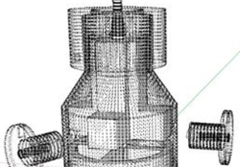
A 3D printed brushless motor is a motor in which some of the mechanical components are fabricated with additive manufacturing, usually on an FDM printer. In most builds, the printable parts include the rotor carrier, stator frame, coil formers, housing, bearing mounts, spacers, alignment tools, and sometimes a fan or cooling shroud. The non-printable parts usually include copper windings, permanent magnets, bearings, shafts, fasteners, adhesives, and, in better-performing designs, steel or iron components that help direct magnetic flux.
That distinction matters. A motor is not just a spinning sculpture. It is an electromagnetic machine. Plastic can shape geometry beautifully, but it does not replace copper’s conductivity, neodymium’s magnetic strength, or steel’s ability to carry magnetic flux. That is why the best 3D printed motor projects treat the printer as a powerful manufacturing tool, not a magic wand.
In other words, a 3D printed brushless motor is usually not a “fully plastic motor.” It is a hybrid device that combines printed structures with traditional electromechanical materials. That is not a flaw. That is the point. Additive manufacturing lets builders customize form, speed up iteration, and make motor geometries that would otherwise be annoying, expensive, or downright rude to machine by hand.
How a Brushless Motor Actually Works
Stator, Rotor, and Magnetic Interaction
A brushless motor converts electrical energy into rotational motion using magnetic fields. The stator stays still and contains coils of wire. The rotor spins and usually carries permanent magnets. When current is switched through the stator windings in the correct sequence, the stator creates a rotating magnetic field. The rotor follows that field, and the shaft turns.
The key word here is sequence. Unlike a brushed DC motor, a BLDC motor does not rely on physical brushes and a commutator to swap current at the right time. Instead, the switching is handled electronically. That is why brushless motors are known for better efficiency, less mechanical wear, lower maintenance, and strong performance in applications where speed control matters.
Electronic Commutation
Electronic commutation is the brains of the operation. A controller energizes motor phases in a timed pattern so the magnetic field keeps pulling the rotor forward. In simple three-phase BLDC systems, this often happens in six basic steps over each electrical cycle. More advanced systems use sinusoidal control or field-oriented control to run more smoothly and efficiently.
Without that control system, your beautiful motor is basically a very expensive paperweight with excellent concentricity. The motor, the driver, and the control method are a package deal.
Why Brushless Motors Are So Popular
Brushless motors are common in drones, fans, e-bikes, power tools, robotics, pumps, and industrial systems because they can offer strong power density, fast response, and long service life. They also avoid brush wear, which eliminates a classic failure point. For makers, that makes brushless motors especially appealing: they are modern, efficient, and just complex enough to make success feel heroic.
What Parts Can Be 3D Printed?
The Printable Winners
Some motor parts are excellent candidates for 3D printing. Rotor shells and magnet carriers are often printed because they benefit from custom slots, exact magnet spacing, and lightweight geometry. Stator supports and coil formers are also strong candidates because they need accurate alignment more than they need exotic material properties. Housings, end caps, mounting plates, and fan blades are almost begging to be printed.
3D printing also shines when a builder wants to prototype motor topology. Need to test a different pole count? Want to change the distance between magnets and coils? Curious whether an axial flux layout fits your compact robot better than a radial flux one? A printer makes those experiments faster, cheaper, and far less emotionally dramatic than machining everything from scratch.
The Parts That Still Want Metal
Then there are the parts that do not appreciate being replaced by enthusiasm. Windings still need copper. High-performance rotors still need strong permanent magnets, usually neodymium. Bearings still need precision metal surfaces. Shafts still need stiffness. And the magnetic path often benefits enormously from ferromagnetic material such as laminated steel or other iron-rich components.
This is where many first-time builds get humbled. A printed stator may look excellent, but if it cannot guide magnetic flux well, torque drops, efficiency suffers, and heat becomes a frequent and unwelcome houseguest. Iron-filled or magnetic filaments can help in some cases, but they are not a drop-in replacement for proper laminated electrical steel.
Axial Flux vs. Radial Flux: The Shape of the Build
Many maker-friendly 3D printed brushless motors use an axial flux design. In simple terms, the magnets face the coils like plates rather than wrapping around them like a cylinder. This arrangement can be easier to assemble with printed parts because the rotor disk and stator disk are mechanically straightforward. It also gives builders good access during winding, balancing, and testing.
A radial flux motor, by contrast, looks more like the classic cylindrical motor people expect. It can be compact and familiar, but it is often trickier to print and assemble cleanly when tight air gaps and round alignment matter. That is why so many hobby builds lean toward axial layouts for educational or experimental projects.
There is no universal winner. Axial flux can offer attractive power density and cooling advantages in some applications, while radial flux remains common and well understood. The best choice depends on your design goals, fabrication limits, controller strategy, and whether your printer behaves like a trustworthy machine or a moody co-worker.
Materials and Design Choices That Matter
Magnets
Magnet selection can make or break performance. Neodymium magnets are popular because they provide high magnetic flux in a compact size. Their arrangement matters too. Some advanced hobby builds use a Halbach-style layout to intensify the field on one side of the rotor. That can improve performance, but it also raises the build difficulty. Getting the orientation wrong is the motor-building equivalent of assembling a puzzle upside down.
Windings
The copper windings determine resistance, current handling, and how much magnetic field the stator can generate. Builders need to think about wire gauge, turn count, coil consistency, and insulation. More turns can increase voltage characteristics but may also raise resistance. Fewer turns may support higher current but can change speed and torque behavior. A sloppy winding job usually shows up later as uneven performance, vibration, heat, or all three in an annoying little bundle.
Air Gap and Alignment
The air gap between the rotor magnets and stator coils is one of the most important dimensions in the entire build. Too large, and magnetic coupling weakens. Too small, and the rotor may rub, wobble, or decide that smooth operation is optional. This is where 3D printing tolerance, shrinkage, and warping become real engineering variables rather than minor inconveniences.
Heat and Mechanical Strength
Motors generate heat. Printed plastics do not always enjoy heat. PLA may be easy to print, but it is rarely the best choice for a motor that sees sustained load. PETG, nylon, polycarbonate blends, or temperature-resistant engineering filaments are often better choices for structural parts. Even then, printed parts near the windings or magnets need thoughtful design. Poor thermal management can soften mounts, loosen adhesive joints, and reduce magnet performance over time.
The Electronics: Where the Motor Either Sings or Sulks
A brushless motor needs a controller, often an ESC or a dedicated BLDC driver. The controller energizes the phases in sequence and may rely on Hall sensors, encoders, or sensorless back-EMF detection. Sensorless systems are common and elegant, but startup can be more challenging because the controller has limited information before the rotor begins moving.
For hobby use, a standard ESC can be enough to spin a custom motor if the winding and electrical characteristics are in a compatible range. For serious development, engineers often move toward custom control boards, tuning, and more advanced commutation strategies. Trapezoidal commutation is simpler and common. Sinusoidal control and field-oriented control tend to improve smoothness, efficiency, and acoustic behavior, but they also raise the complexity.
This is one reason a 3D printed brushless motor is such a good educational project. It forces builders to see the full system: mechanics, magnetics, electronics, software, and thermal behavior. It is not just “print part, push button, become Nikola Tesla.” There are several steps in between.
How Well Can a 3D Printed Brushless Motor Perform?
The honest answer is: it depends on the design and on what you mean by “perform.” For classroom demonstrations, low-load mechanisms, and rapid prototyping, printed brushless motors can be fantastic. They make motor geometry visible, understandable, and customizable. They also give hobbyists a rare opportunity to test design ideas directly rather than imagining them in CAD forever.
For serious power applications, the bar rises fast. Some maker projects have demonstrated impressive results, including multi-hundred-watt motors and high rotational speeds. At the same time, experiments with heavily printed magnetic components have shown the limits clearly: lower torque, thermal issues, and weaker magnetic performance compared with designs that still use traditional steel laminations and carefully optimized magnetic paths.
That does not make the project a gimmick. It simply means the best 3D printed motor is often the one that prints the right things, not everything. Smart hybridization wins. Print the geometry. Buy or fabricate the materials that physics still prefers. Let plastic handle structure where appropriate, and let copper, steel, and magnets do the jobs they were born to do.
Where These Motors Make Sense
A 3D printed brushless motor makes a lot of sense in education, research, rapid prototyping, robotics experiments, artistic kinetic installations, and custom low-volume projects. It is especially useful when unusual geometry matters more than mass production. If you need a one-off motor housing for a lab prototype, a custom axial-flux concept for a student project, or a visible working model for teaching electromagnetic principles, additive manufacturing is a gift.
It makes less sense when you want the cheapest, highest-reliability motor for mainstream use. If your goal is simply to power a drone, a skateboard, or a pump with proven hardware, off-the-shelf motors are hard to beat. They benefit from industrial lamination stacks, mature manufacturing, better balancing, tested insulation systems, and quality control that does not depend on whether your nozzle was slightly clogged on Tuesday.
Conclusion
A 3D printed brushless motor is not a toy, but it is not a miracle either. It is a fascinating blend of digital fabrication and classic electromechanics. At its best, it turns abstract engineering into something you can hold, measure, tune, and improve. It teaches why brushless motors are efficient, why magnetic materials matter, and why control electronics are every bit as important as the spinning hardware.
The most successful builds do not try to replace every traditional material with plastic. They use 3D printing strategically, where customization, speed, and geometry provide real value. That is the real lesson. Additive manufacturing does not cancel engineering fundamentals; it puts them on full display. And that is exactly why these motors are so interesting. They are practical enough to work, demanding enough to teach, and cool enough to make even seasoned builders grin when the rotor finally spins the way it was supposed to on the first try. Or, more realistically, on the fourth.
Experiences From Building and Testing a 3D Printed Brushless Motor
Anyone who has spent time around a 3D printed brushless motor project will tell you that the experience is half engineering exercise and half personality test. On paper, the process looks straightforward: print the parts, wind the coils, install the magnets, add bearings, connect the controller, and enjoy the smooth whir of your custom machine. In reality, the project teaches patience faster than a motivational poster ever could.
One of the first experiences builders talk about is how quickly they stop thinking of the printer as a gadget and start treating it like a manufacturing tool. A rotor disk that is off by a fraction of a millimeter can wobble. A stator mount with slight warping can widen the air gap enough to sap performance. Magnet pockets that seem perfect in CAD can be just tight enough in real life to turn assembly into a negotiation with epoxy and gravity. It is a project that rewards careful measuring, test fitting, and the humble habit of printing one small section before committing to a full overnight run.
Winding coils is another memorable chapter. At first it sounds relaxing, almost meditative. Then you reach the point where every turn has to stay neat, tension matters, and your fingers discover that magnet wire has a secret talent for becoming tangled at emotionally strategic moments. Builders often say that coil winding is the moment when the project stops feeling like 3D printing and starts feeling like motor building. Because that is exactly what it is.
Then come the magnets. If you have never handled a set of strong neodymium magnets in close quarters, a motor project will fix that. They snap together, jump toward tools, and occasionally make you question your life choices. Alignment matters, polarity matters, and balance matters. The first time a builder realizes one magnet is flipped the wrong way after the adhesive has already cured, the lesson tends to become permanent.
The most satisfying moment usually comes during first spin-up. Sometimes the motor runs immediately and produces a clean, confident rotation that makes the whole workshop feel smarter. Other times it jitters, stalls, squeals, or gets hot in the sort of way that inspires a very fast hand withdrawal. Oddly enough, even those disappointing tests are valuable. Builders learn to diagnose phase wiring, timing, friction, poor coil symmetry, weak airflow, and controller settings. The project becomes less about making one perfect object and more about understanding a system.
That may be the biggest experience-related takeaway of all: a 3D printed brushless motor teaches iteration. Rarely does version one become the final version. Builders change the coil count, tweak the magnet spacing, stiffen a mount, swap materials, improve the bearing seats, or redesign the cooling path. Every revision gets smarter. And because the core structure is printable, those improvements are actually accessible.
In the end, people remember these projects not just because the motor spins, but because the motor explains itself while it spins. You can see the geometry. You can trace the design decisions. You can connect performance problems to physical causes. That makes the experience unusually rich. It is not just fabrication. It is hands-on proof that good engineering is built from repeated observation, thoughtful changes, and a willingness to laugh a little when the first prototype behaves like a confused blender.